18.12.09
WHO RUNS BARTER TOWN???
some additions to the MASTERBLASTER article have been added, including a new layout and some new mod ideas. you will be redirected to the article by clicking on this entry's title.
29.11.09
WAMPLER - CRANKED AC
recently while browsing a certain clone kit site, i stumbled across the schematic for brian wampler's cranked ac design. having been on a serious ac kick a while back, i was never able to find the schematic, so this was kind of a cool find. the cranked ac at first looks like your run of the mill jfet type distortion box until you notice that wierd parallel fet configuration. ecaxtly what this is supposed to do to the sound i don't know, but it is a rather interesting little tweak. i'm sure that this could be adapted to just about any transistor type, and wonder if it has any of the same kind of properties as stacking ic's.
i redrew the schematic and made up an eagle verified pcb layout which should work ok. if anyone gets it built please let me know . you can keep up with all of the latest on this subject HERE.
XXXXXXXXXXXUPDATEXXXXXXXXXXXX
LAYOUT IS VERIFIED!


XXXXXXXXXXXUPDATEXXXXXXXXXXXX
LAYOUT IS VERIFIED!


28.11.09
LISSAJOUS FIGURE VID
browsing the really cool EXPERIMENTALIST ANONYMOUS BLOG, i found this great video of a LISSAJOUS FIGURE portrayed on an oscilloscope. from what i gather, a lissajous figure can be generated using a scope by injecting one wave ionto the x axis, and another onto the y axis. summing them together, you get this 3D effect. the maker of the video put the left channel through the x axis, and the right through the y, all the while tweaking multiple effects. as i finally picked up a scope recently, i find this sort of thing fascinating. unfortunately, the cheapo 40 dollar scope i got only has a single channel, so you won't be seeing any lissajous figures from me in the near future.
27.11.09
SOME COOL PARTS SOURCING SITES
here are a few kick ass sites to source parts on the cheap. the first is EVITA. they are a great source for any russian parts that you might want, and are even cheaper than what you can find them for on ebay. plus you don't have to buy a box of 100 of a single type, you can mix and match as you please. i have heard that they have reasonable shipping, and EVITA has all of the datasheets available for download on there sight, so you have some idea of what you are getting into.
as you can probably tell, i have a serious passion for these russkie germanium trannies, as many types are about as consistent as any silicon transistor out there, and unlike euro, american, or japanese trannies, many types have absolutely no leakage. the consistency of russian ge transistors is pretty much unparalleled around the world. i think this must be due to the fact that the soviets were producing germaniums well into the 80's where other sources had stopped long before. also they used them for many military uses as well, so their standards were set very high. you can tell the transistors and other parts meant for military use as they have a small diamond printed on the side.
along with transistors, there are many excellent russian teflon, paper in oil, and polystyrene capacitors offered at EVITA, so if you have an urge for cheap, quality soviet parts, now you don't have to be a slave to ebay.
if you have ever built an analog delay, you know how hard it is to source bucket brigade delay chips. you can end up paying a hefty price for what may end up being total counterfeit crap. you can go to a parts sourcer, but there may be a large minimum order that puts buying the parts well out of your price range. well, i recently was turned on to UTSOURCE, who source hard to find, out of production parts with very small minimum orders and good prices to boot. give em a shot if there are some rare chips you can't find.
lastly, is TEDDS.COM. they have lots of cool vintage capacitors and other parts with only a ten dollar minimum. also, they have pics of every cap in their inventory so you don't have to have every model number memorized. good stuff.
26.11.09
EFFICIENT CALCULATOR USE FOR ELECTRONICS FORMULAE
HERE is a great post by electronics wizard Tonmann over at the circuit workshop forum. it breaks down and totally demystifies the process of working on electronics formulas. it's a great little tutorial, and hopefully, tonmann will have his larger tech tutorial done soon.
OPAMP BASICS
mystified by that tube screamer? in a conundrum over the klon? THIS course at Elliot Sound Products has all of the basics about opamps covered. all the common configurations, power applications, filters, and formulae are there for the taking. they have a shitload of other great articles and projects over there too, so be sure to check out the rest of the site.
FREE ELECTRONICS BOOKS
8.11.09
3PDT DAUGHTER BOARDS
recently i've gotten right sick of trying to jam my nice, thick, 22 gauge, solid core wire into switch contacts. many times i'd end up marring the insulation, or just not liking the appearance. a remedy was to design a daughter board to connect all of the wires to the switch. after a bit of talk with my friends over at FSB, i decided to expand on the idea, and built a few different versions. V1 is a simple board with connections for each lug on the switch. V2 has a resistor added for limiting the power to the LED. version 2.1 adds a pad for connecting DC and the other side of the LED. finally, V3 adds to this a spot for a power filtering electrolytic capacitor, and polarity protection diode. in the future i may add more designs, possibly adding R.G. Keen's MOSFET polarity protection scheme, and a voltage divide for use with op amp circuits. there has also been some talk of making a group buy for printed PCBs. we'll see if that ever comes to pass in the future. you can check out all of the layouts and keep abreast of the latest news HERE.


6.11.09
MONTARBO PB-2 FUZZ SECTION
hey if anyone is out there, sorry it's been so long. been kinda denying the blog love lately, hope to get back into it with some cool stuff to add.
here is a little italian fuzz circuit that i thought looked interesting. it's from the montarbo pb-2 fuzz/phaser combo pedal. i like the negative feedback diode configuration. at first it looks a bit like a muff, but there are some differences when you look closer. you can see that the diode loops are separated by capacitors effectively isolating them from the DC that is used to bias the transistors, where as in the big muff, the diodes have their own dedicated blocking caps, filtering the frequencies to be clipped. also, there is a 47K resistor to ground on the first tranny's diodes that may introduce some harsher clipping by pulling the diodes closer to earth. it looks like a fun little way to adjust clipping, and i plan on giving it a shot in the future. if anything cool comes of it, i'll be sure to let you know on the blog.
cheers!

26.8.09
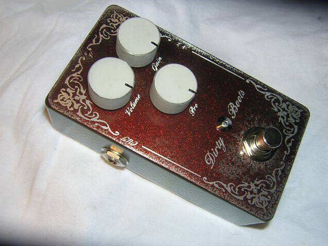
ELEKTRATONE'S DIRTY BOOTS
FSB forumite elektratone built up this cool rust finished version of the dirty boots a while ago. i thought it was about time he got some fame on the blog. it definitely looks like this thing's been through the apocalypse and back!


24.8.09
FREESTOMPBOXES.ORG MONTHLY CIRCUIT ANALYSIS
the first installment of the FSB Monthly Circuit Analysis is up and running! check out the dirt on the Maestro Fuzz-Tone. there are circuit analysis, links to clips, patents, experiments, explanations, and tons of other cool stuff regarding the first ever fuzz box made. hopefully this will turn into a long standing tradition at FSB, as we explore the other creations throughout the pantheon of guitar effects. check it all out HERE.
7.8.09
COLORSOUND DEALER BOOTH
i just thought i'd post this great pic of the colorsound booth from a convention in the early seventies. it was so cool, i just had to show off those funky displays. enjoy the shag!


20.7.09
APOCALYPSE AUDIO - PANZER FUZZ
my latest creation is an uber-high gain fuzz-tortion designed around the soviet GT308B germanium transistor. since this seems like one of the more common russian germanium transistors that people buy, i thought it would be a good candidate to include in my next project. the 308B has a gain that usually hovers around 75 in most specimens that i have seen, except for some batches marked with red dots that have a gain of around 20 points less on the Hfe reading. as with most other soviet Ge's, their leakage is pretty much nil, this allows for excellent stablilty, easy biasing without trimpots, and no need to do tedious gain/leakage checks. i thought the 308 would be the perfect candidate to design a high gain fuzz around because of it's relatively high gain compared to other russian Ge's, and i haven't done anything along those lines since the Toecutter, which although it is doomy as hell, it is in itself not all that terribly high gain anyway.
the controls of this guy are as follows- gain, lo drive, hi drive, tone, and volume. the lo drive control is basically a full range gain control for the 2nd stage, and the hi drive control is i gain control for the 3rd stage that is concentrated only on the high frequencies. with all of the gain and drive controls turned up, you get an all out doomy grind with plenty of bite for on the top end. rolling back the gain control gives you a great crunch tone that i would describe as medium-high gain. the tone control is a heavily modified version of one that i saw on the AMZ site. i added 2 more caps, and adjusted all of the values for a nice even sweep. turning it all the way up also brings in a little bit of low end as well, so you get what sounds like a little dip in the midrange, too- adding to the metal tone of circuit. don't get me wrong though- this isn't one of those ultra-scooped metal zone P.O.S.'s. this thing has a ton of low end and has been tuned to have a bump in the high mids as well in order to cut through the mix and add some nice grind to the tone.

i did this write up of the basics of the schematic for culturejam's new circuit design forum circuitworkshop.com.
it can be found HERE.
the input cap(.033) was chosen to roll off just the bottom end of the input signal, there will be plenty more of that to come. the first stage is a basic booster using feedback biasing(1M resistor), and a .47 uF bypass cap for more gain throughout the full frequency range of the guitar. the emitter resistor(1K) was chosen to limit the amount of output from the first stage, and the 470pF cap rolls off some highs and stabilizes any oscillations that might happen.. next we have the gain pot(500K) and a 2K2 resistor setting the minimum amount gain available. the .01/220K combo allows highs to pass easier than lows trimming some of the fat off of the boosted signal. stage 2 is biased the same, as is stage 3. i find this technique of biasing easy and simple, allowing for fewer components as well. the .047uF cap rolls some high end off of this stage. the lo drive pot is a 10k pot going through a 47uF cap to ground. this isn't really just low end getting boosted per se, more of a full range gain control for this stage, but with the lows rolled off by the .o47 cap it definitely has some of that feel to it. the 100K/.1uF combo are doing negative feedback duty, reducing the overall gain a bit, as well as taming some noise and adding stability. next, the .0047 cap is more low pass filtering, and the .068 is hi pass,interstage coupling, and DC blocking. stage 3 also has some more high end filtering grom the .0022 cap to the 9V rail, and the bias values have been tweaked by ear a little. the hi drive pot is a 1K connected to ground through a 100uH inductor. turning this up adds a decent amount of sizzle to the sound. the 680/.1uF to ground were added to round out the frequency response of this stage a bit. the tone control is a tweaked version of jack orman's swtc2. i changed some values and added the .0033 and .01 cap to ground. the final .001 cap is rolling off a bit more of the very top end. finally the volume control has a 2K2 resistor to ground to limit it's lowest value. the mosfet and 1M resistor are there for reverse polarity protection, and the 100uF cap is for power filtering.
attached is a pcb layout, that is of yet unverified, but it has been checked in eagle, so it should be good. i'm going to try and get some clips done soon- they won't be the highest of quality though, but you should be able to get the idea of what is going on. hope someone out there can give this one a shot- it's really a killer!
XXXXXXUPDATEXXXXXX it looks like the size printed on the layout is a bit small. if you measure it out to that size, then increase by 10% you'll be perfect. sorry about that!

the controls of this guy are as follows- gain, lo drive, hi drive, tone, and volume. the lo drive control is basically a full range gain control for the 2nd stage, and the hi drive control is i gain control for the 3rd stage that is concentrated only on the high frequencies. with all of the gain and drive controls turned up, you get an all out doomy grind with plenty of bite for on the top end. rolling back the gain control gives you a great crunch tone that i would describe as medium-high gain. the tone control is a heavily modified version of one that i saw on the AMZ site. i added 2 more caps, and adjusted all of the values for a nice even sweep. turning it all the way up also brings in a little bit of low end as well, so you get what sounds like a little dip in the midrange, too- adding to the metal tone of circuit. don't get me wrong though- this isn't one of those ultra-scooped metal zone P.O.S.'s. this thing has a ton of low end and has been tuned to have a bump in the high mids as well in order to cut through the mix and add some nice grind to the tone.

i did this write up of the basics of the schematic for culturejam's new circuit design forum circuitworkshop.com.
it can be found HERE.
the input cap(.033) was chosen to roll off just the bottom end of the input signal, there will be plenty more of that to come. the first stage is a basic booster using feedback biasing(1M resistor), and a .47 uF bypass cap for more gain throughout the full frequency range of the guitar. the emitter resistor(1K) was chosen to limit the amount of output from the first stage, and the 470pF cap rolls off some highs and stabilizes any oscillations that might happen.. next we have the gain pot(500K) and a 2K2 resistor setting the minimum amount gain available. the .01/220K combo allows highs to pass easier than lows trimming some of the fat off of the boosted signal. stage 2 is biased the same, as is stage 3. i find this technique of biasing easy and simple, allowing for fewer components as well. the .047uF cap rolls some high end off of this stage. the lo drive pot is a 10k pot going through a 47uF cap to ground. this isn't really just low end getting boosted per se, more of a full range gain control for this stage, but with the lows rolled off by the .o47 cap it definitely has some of that feel to it. the 100K/.1uF combo are doing negative feedback duty, reducing the overall gain a bit, as well as taming some noise and adding stability. next, the .0047 cap is more low pass filtering, and the .068 is hi pass,interstage coupling, and DC blocking. stage 3 also has some more high end filtering grom the .0022 cap to the 9V rail, and the bias values have been tweaked by ear a little. the hi drive pot is a 1K connected to ground through a 100uH inductor. turning this up adds a decent amount of sizzle to the sound. the 680/.1uF to ground were added to round out the frequency response of this stage a bit. the tone control is a tweaked version of jack orman's swtc2. i changed some values and added the .0033 and .01 cap to ground. the final .001 cap is rolling off a bit more of the very top end. finally the volume control has a 2K2 resistor to ground to limit it's lowest value. the mosfet and 1M resistor are there for reverse polarity protection, and the 100uF cap is for power filtering.
attached is a pcb layout, that is of yet unverified, but it has been checked in eagle, so it should be good. i'm going to try and get some clips done soon- they won't be the highest of quality though, but you should be able to get the idea of what is going on. hope someone out there can give this one a shot- it's really a killer!

XXXXXXUPDATEXXXXXX it looks like the size printed on the layout is a bit small. if you measure it out to that size, then increase by 10% you'll be perfect. sorry about that!

7.7.09
freestompboxes manifesto
i thought i'd print this bit of text that explains how and why my favorite forum- freestompboxes.org- was created. here ya go, the Freestompboxes Manifesto!
Freestompboxes.org Mission Statement (June 17th, 2007) Another Forum? It really takes nothing to set up a forum nowadays... No money, no knowledge, just a borrowed computer will do. There are more then plenty of them on every subject all over the internet. Probably rightfully so, because newsgroups and forums are the heart of the internet: people from all over the world with the same interest have the opportunity to exchange ideas. With libraries abound, the internet did not do so much of spreading the canon of official canonical information. Rather, it turned out to be a great medium for the exchange of underground stuff. Building your own guitar effect stompbox is a prime example. Stompbox project Info on the internet Most of the circuits have been around since the beginning, but mostly in DIY magazines and they never really caught the guitarists' eye. They just walked in and grabbed their Guitar Player magazine. The online guitarist googling for 'vintage stompboxes' nowadays is bound to meet the DIY stompbox community sooner or later. And if you are true tonefreak rather then a show-off name dropper you get very happy at the thought that you can build your own 'boutique' stompbox and tweak it to your own taste for a fraction of the money you would pay for a boutique box. Backlash of the DIY pedal craze Big commercial pedal manufacturers are dropping their prices like they're hot, boutique pedal makers are getting nervous and begging the diy community to safeguard them certain commercial death. Or so they think... Recent turbulences and censorship of certain commercial schematics (although they are all over the net) has caused great upheaval at the mother of all stompboxsites, aron's diystompboxes.com causing some 'heretic' discussion to flee to the kind German Musikding.de forum. Copyright, Patent and more Of course often the artwork and the graphical layout of the pcb of effect are protected, but redrawing or tracing a circuit is by no means illegal. Patents on effects do exist, but they are not some common. Most of them have expired by now. There are some examples here on the forum, so do check them out in you are interested. Maybe this quickly setup board can provide a space for unabridge, free discussion about any stompbox design.
Freestompboxes.org Mission Statement (June 17th, 2007) Another Forum? It really takes nothing to set up a forum nowadays... No money, no knowledge, just a borrowed computer will do. There are more then plenty of them on every subject all over the internet. Probably rightfully so, because newsgroups and forums are the heart of the internet: people from all over the world with the same interest have the opportunity to exchange ideas. With libraries abound, the internet did not do so much of spreading the canon of official canonical information. Rather, it turned out to be a great medium for the exchange of underground stuff. Building your own guitar effect stompbox is a prime example. Stompbox project Info on the internet Most of the circuits have been around since the beginning, but mostly in DIY magazines and they never really caught the guitarists' eye. They just walked in and grabbed their Guitar Player magazine. The online guitarist googling for 'vintage stompboxes' nowadays is bound to meet the DIY stompbox community sooner or later. And if you are true tonefreak rather then a show-off name dropper you get very happy at the thought that you can build your own 'boutique' stompbox and tweak it to your own taste for a fraction of the money you would pay for a boutique box. Backlash of the DIY pedal craze Big commercial pedal manufacturers are dropping their prices like they're hot, boutique pedal makers are getting nervous and begging the diy community to safeguard them certain commercial death. Or so they think... Recent turbulences and censorship of certain commercial schematics (although they are all over the net) has caused great upheaval at the mother of all stompboxsites, aron's diystompboxes.com causing some 'heretic' discussion to flee to the kind German Musikding.de forum. Copyright, Patent and more Of course often the artwork and the graphical layout of the pcb of effect are protected, but redrawing or tracing a circuit is by no means illegal. Patents on effects do exist, but they are not some common. Most of them have expired by now. There are some examples here on the forum, so do check them out in you are interested. Maybe this quickly setup board can provide a space for unabridge, free discussion about any stompbox design.
4.5.09
TRIODE FUZZ 1 & 2
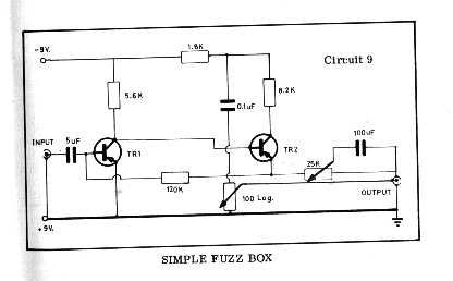
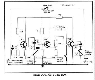
here in chicago we have a cool electronics shop called triode electronics. in the amazing mess that is triode, there is a virtual plethora of parts and supplies for the DIY enthusiast. on the store's website there are a number of interesting circuit schematics and articles, and i found these two little fuzz circuits there. one is very similar to the fuzzface, and the other looks like a pretty interesting sixties style fuzz box. i'm not sure where they come from, but they look pretty cool, and are worth giving a try. who knows, it could be the next fuzz factory!


21.4.09
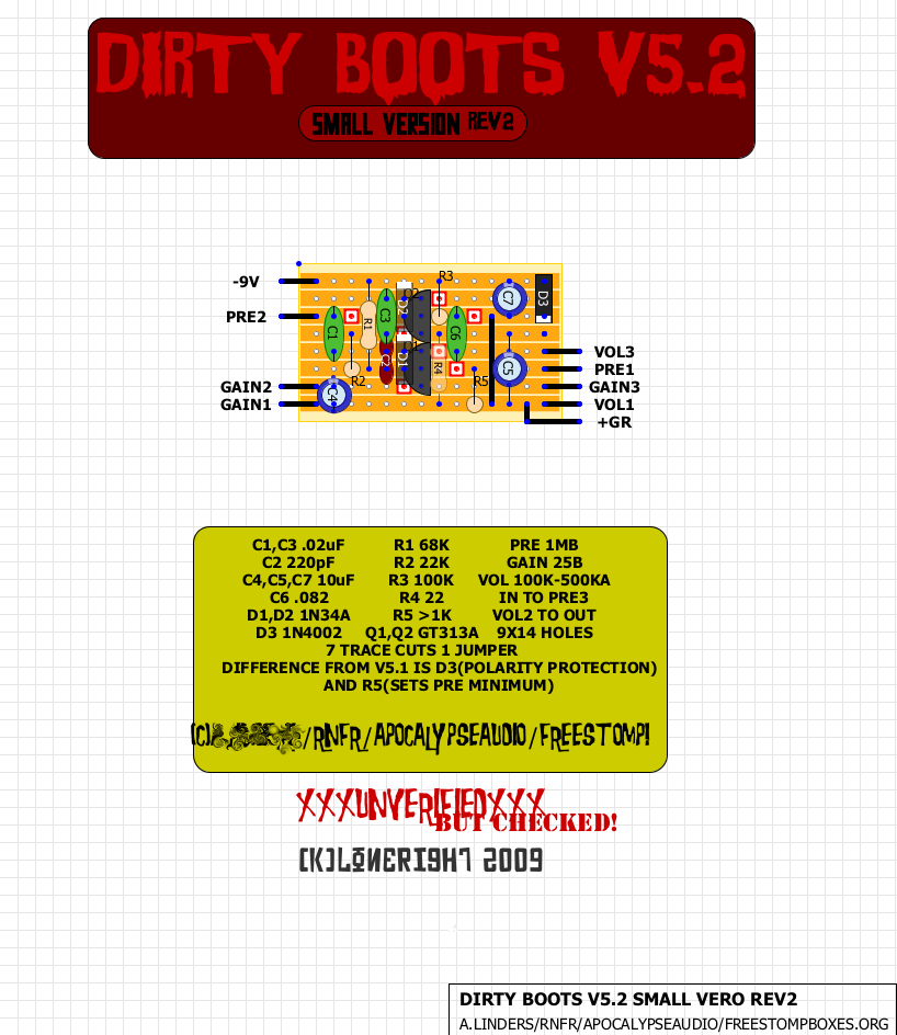
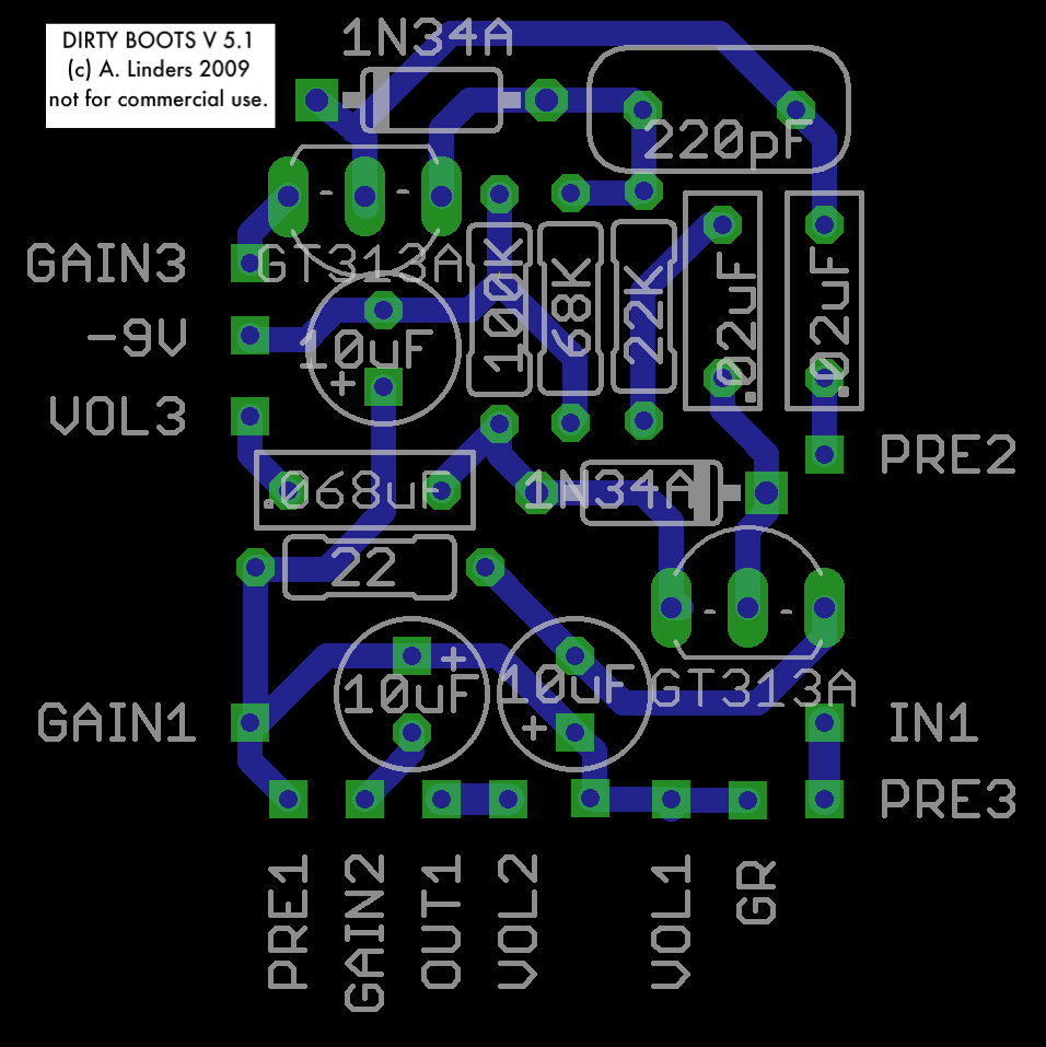
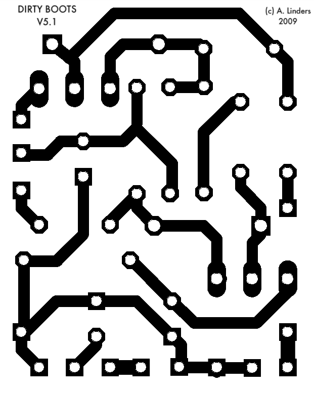
2, NO, 3! NEW DIRTY BOOTS VEROS!
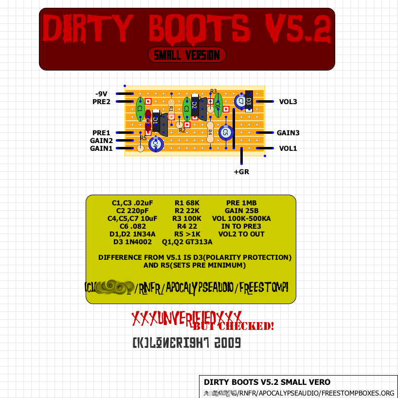
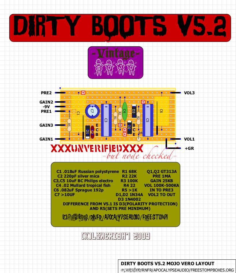
dudes! made up a few new veros for the db. the first one is a small layout for box caps and radial electros for you guys that like those little baby boxes. the second one is for axial caps vintage style and specifies the specific type of caps that i have been using for my builds. of course, sprinkle your mojo to taste. i'm callin this on v5.2 because of the added reverse polarity protection diode as well as a limiting resistor for the pre control. haven't decided at the exact value for that one, most likely around 50-100K, or just put lug one straight to ground like before. the third one is just stupid small. i call it rev2. good luck you masochists! take er easy!


17.4.09
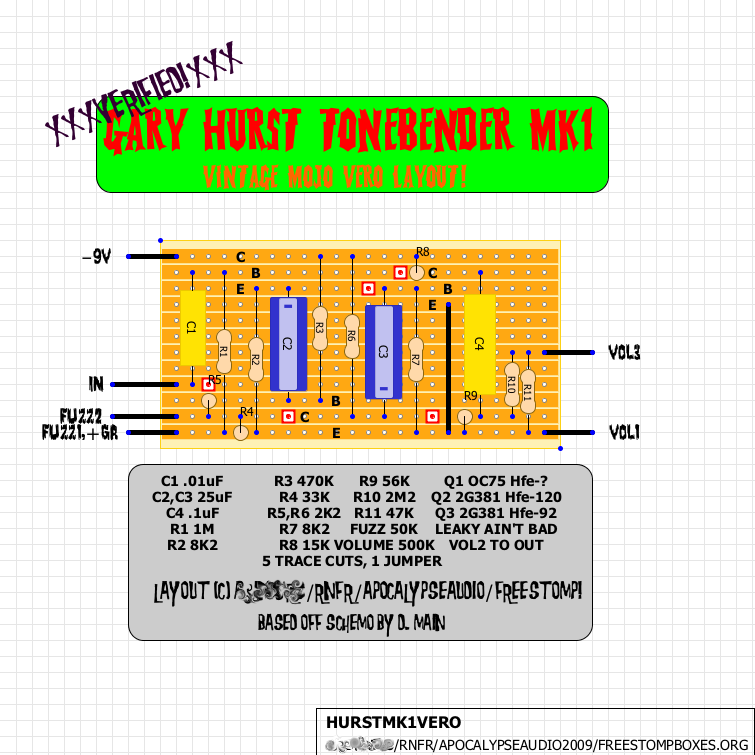
GARY HURST MK1 VERO LAYOUT
here's a layout i made up today while trying to stay awake at one of my corporate gigs. it's for gary hurst's version of the tonebender mk1. a kind of finnicky crcuit, it is said to work best with leaky trannies, we'll see when i throw it on the old breadboard later. looking forward to building this one up after i heard some killer clips at the DAM forum. the layout can be easily changed to vintage specs as well, if that's the one you are after. the schemo can be found HERE.
XXXXXXUPDATEXXXXXX layout is now verified! try a 1M resistor in place of the 2M2 for more output.
here is a shitty pic of the verified board.
XXXXXXUPDATEXXXXXX layout is now verified! try a 1M resistor in place of the 2M2 for more output.

here is a shitty pic of the verified board.

15.4.09
i've been promoted!
the fine minds over at freestompboxes.org have deemed me worthy of modhood! that's right, yours truly was dubbed moderator over at the coolest diy guitar effect pedal site on the interwebs! holy fuck, i'm cool! now seriously, all you slags watch your back cuz there's a new man with a badge in stomptown and he ain't takin no prisoners. search first, or straight to the klink witcha!!!
26.3.09
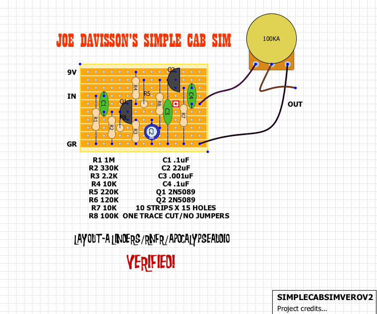
JOE DAVISSON'S SIMPLE CAB SIM VERO LAYOUT
i made up this layout and built this up tonight so that i could work on fuzz designs in my headphones late at night. layout is verified.
schematic can be found HERE.
schematic can be found HERE.

25.3.09
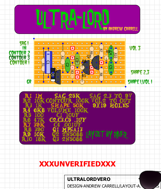
TONE FACTOR ULTRA LORD VERO LAYOUT
the ultra lord is a high gain fuzz that was created by andrew carrell and licensed to the Tone Factor brand. i haven't had a chance to build it yet, but apparently it sounds awesome. the origin of the circuit is originally based of a circuit called the dirty sanchez which carrell designed in order to have something that was a cool sounding, high gain fuzz, made from easily available radio shack parts. the ultra lord is a tweaked version of the dirty sanchez apparently taking it's sound to it's full potential. the UL looks to me like a bazz fuss running into a darlington pair with a mark hammer modded shin-ei fy-2 style mid scoop control on the end and a sag pot for the voltage. a combo of some nice snippets. here is vero layout that i made- it is unverified, but thoroughly checked. if you make it, let me know!
the schematic can be found HERE.
the thread for the ultra lord at freestompboxes.org can be found HERE.
the schematic can be found HERE.
the thread for the ultra lord at freestompboxes.org can be found HERE.

5.3.09
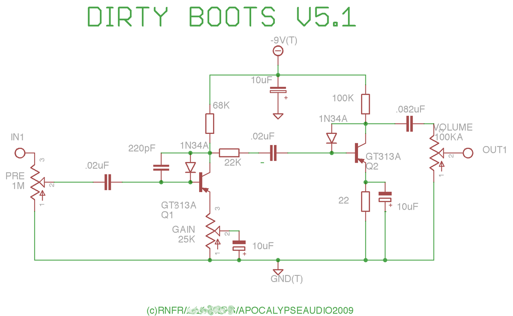
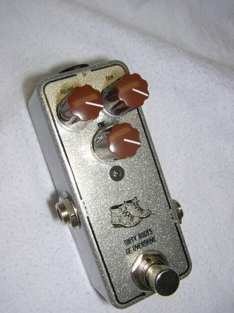
DIRTY BOOTS GERMANIUM OVERDRIVE
this little circuit is really what got me started in the whole DIY effects design process. i needed something that i could use to dirty up a loud, clean amp just enough to where it would have a touch of grit. it's a great little overdrive that can be used as a germanium booster as well as a fuzz if your pickups are hot enough.
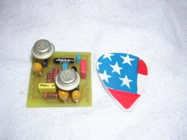
it all started when i decided to breadboard the Trotsky Drive by Beavis Audio, which is basically a GE version of the Electra Distortion with a bias adjustment pot. using a russian GT313A transistor, i was fooling around with it, messing with values and such, when i remembered that the Bazz Fuss uses a diode in the C to B position instead of a resistor like the Trotsky/Electra. so i tried it out, and i got an excellently biased gain stage with just a bit of compression. then i realized that the circuit i was working on was PNP, where the BF is NPN. so the diode configuration is actually reversed. eventually i came to learn, with the help of many generous folks in the DIY community, that the GE diode that i was using was leaky, all of them are leaky, and it is this leakage that is actually acting as a large resistor and biasing the transistor. cool,huh? along with that, i'm sure that the diode is adding it's own little stamp on the situation with a bit of compression an break up.
after messing about with a ton of diodes this way and that, with filtering, in series, etc., i decided that i'm just not that big of a fan of diode clippers. i find them unnatural sounding, and their clipping just sound too "obvious" to me for some reason. so i ditched the clippers, added a small cap from C to B to roll off a bit of highs, and just put a whole nother stage in series with the first.
Lo! the Dirty Boots was born.
eventually i ended up trying a bias pot on the second stage and some different switching options for changing gain and tone, etc., but ended up with a normal emmitter controlled gain stage, a pregain control, and a volume pot. the latest mod was the series resistance between stages and ditching the cap from C to B on the second stage to open it up a bit.
it's really a great sounding little circuit using ge trannies which can be found on the bay for dirt cheap. the basic gain stage can be used for other things as well- it became the basis for The Toecutter.
give it a try sometime, or i'll send my band of mutated hobbit rat people to dig you out of your bomb shelter and eat you for second breakfast.
the thread at FSB about the Dirty Boots can be found HERE.
many thanks go out to Martin Chittum, Marcelo "Mac" Tripodi, and others that helped me understand along the way!
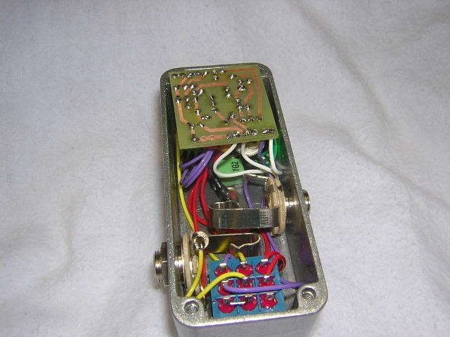
here is a layout using common sized parts. i have another for use with the extra mojo axial caps and such that i will post later.
daniel zink made this great version of the Dirty Boots in a Hammond 1590A box. a little killer!
here's another one from mr. zink- very stylish!
it all started when i decided to breadboard the Trotsky Drive by Beavis Audio, which is basically a GE version of the Electra Distortion with a bias adjustment pot. using a russian GT313A transistor, i was fooling around with it, messing with values and such, when i remembered that the Bazz Fuss uses a diode in the C to B position instead of a resistor like the Trotsky/Electra. so i tried it out, and i got an excellently biased gain stage with just a bit of compression. then i realized that the circuit i was working on was PNP, where the BF is NPN. so the diode configuration is actually reversed. eventually i came to learn, with the help of many generous folks in the DIY community, that the GE diode that i was using was leaky, all of them are leaky, and it is this leakage that is actually acting as a large resistor and biasing the transistor. cool,huh? along with that, i'm sure that the diode is adding it's own little stamp on the situation with a bit of compression an break up.
after messing about with a ton of diodes this way and that, with filtering, in series, etc., i decided that i'm just not that big of a fan of diode clippers. i find them unnatural sounding, and their clipping just sound too "obvious" to me for some reason. so i ditched the clippers, added a small cap from C to B to roll off a bit of highs, and just put a whole nother stage in series with the first.
Lo! the Dirty Boots was born.
eventually i ended up trying a bias pot on the second stage and some different switching options for changing gain and tone, etc., but ended up with a normal emmitter controlled gain stage, a pregain control, and a volume pot. the latest mod was the series resistance between stages and ditching the cap from C to B on the second stage to open it up a bit.
it's really a great sounding little circuit using ge trannies which can be found on the bay for dirt cheap. the basic gain stage can be used for other things as well- it became the basis for The Toecutter.
give it a try sometime, or i'll send my band of mutated hobbit rat people to dig you out of your bomb shelter and eat you for second breakfast.
the thread at FSB about the Dirty Boots can be found HERE.
many thanks go out to Martin Chittum, Marcelo "Mac" Tripodi, and others that helped me understand along the way!

here is a layout using common sized parts. i have another for use with the extra mojo axial caps and such that i will post later.


daniel zink made this great version of the Dirty Boots in a Hammond 1590A box. a little killer!


here's another one from mr. zink- very stylish!

16.2.09
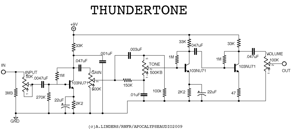
Apocalypse Audio- Thundertone
here's something i churned out the other day. i have been thinking about modeling the Supro Thunderbolt with FETs, but then thought- i just got in these cool new Tesla GE's, why not use those? so that's what it is, the preamp section of the legendary amp used by Page and supposedly Hendrix, done up NPN germanium style. i had to eliminate a few resistors towards the end to bring up the volume and lowered the value of an emitter resistor to up the gain a bit. also, i made the resistor on the input variable so you can adjust the input impedance for guitars with different pickups.
the real gem of this circuit is the tone pot- totally counter-clockwise you get a nice full range tone with plenty of mids. as you go clockwise it goes to a very muffled tone, and as you go even further, it goes to a very thin, cutting tone. there are some very cool sweet spots, and a lot of versatility. i like it better than a regular muff style control, but it does cut plenty of signal- hence the two gain stages after it.
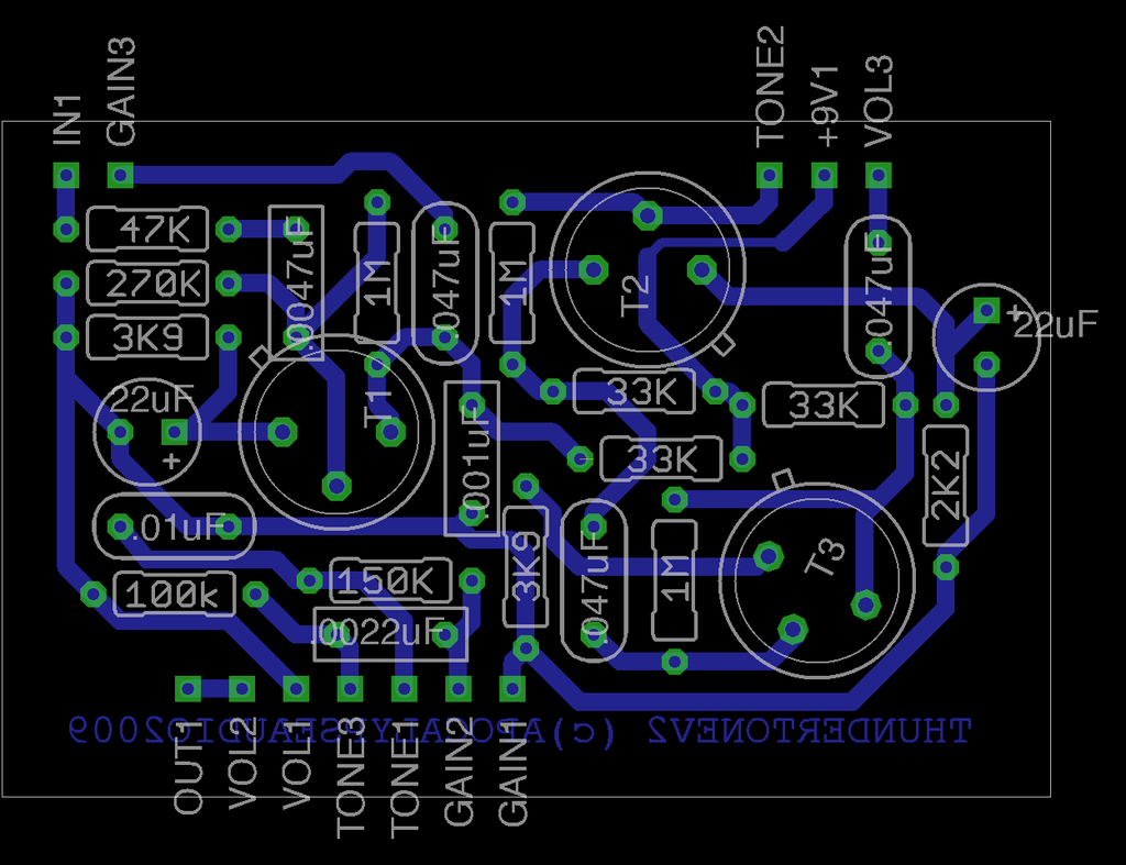
it's a cool sounding circuit. nicely voiced and does a good overdrive type sound. if you don't have the trannys, you could change out the 33K Rc's to trimmers and adjust to taste. the tesla trannies are extremely consistent, so no trimmers needed. the layout below uses some large axial caps and is yet unverified, but hopefully i'll get it done sometime soon.
XXXUPDATEXXX the large parts PCB is being retooled due to infestation of mutant roaches. stay tuned! XXXUPDATEXXX
XXXXUPDATEXXXX i was made aware that there could be DC voltage on the tone pot. you may need another capacitor after it to get rid of crackle that may be present. a .047uF cap off of lug 2 of the pot should remedy this. i'll amend the schem and layout after i do some more experimenting. XXXXUPDATEXXXX
XXXXXXXXXXXXXUPDATEXXXXXXXXXXXXXX I built up the Thundertone with the old mojo parts layout and it works with no tone crackle!I will be revamping it for a tighter layout. XXXXXXXXXXXXXUPDATEXXXXXXXXXXXXXX
take it easy!
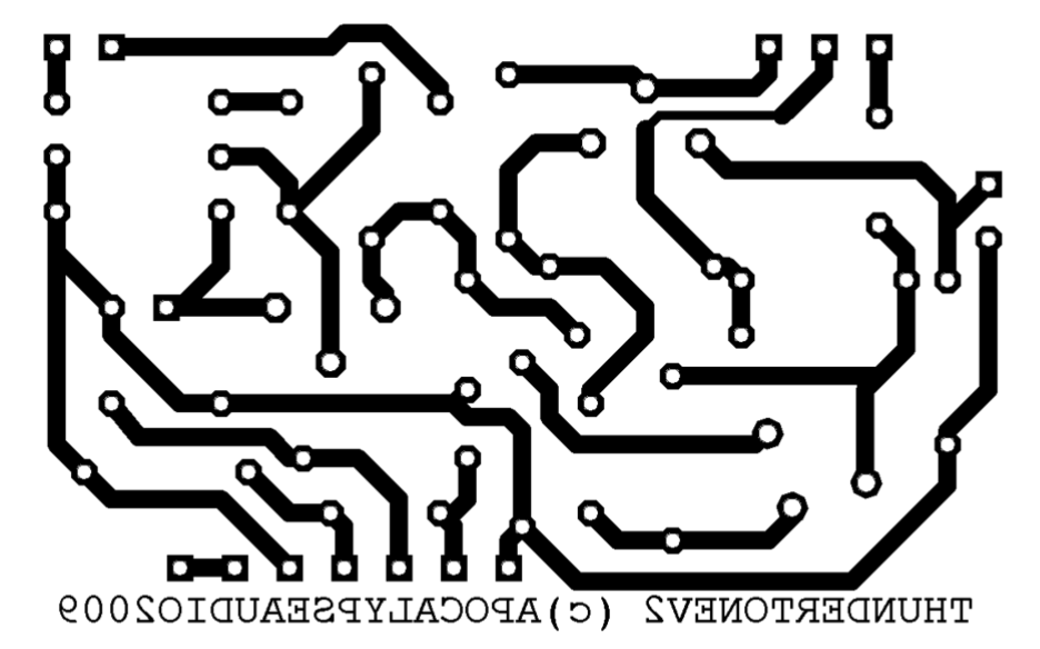
here is a new PCB using common size/value parts.
the real gem of this circuit is the tone pot- totally counter-clockwise you get a nice full range tone with plenty of mids. as you go clockwise it goes to a very muffled tone, and as you go even further, it goes to a very thin, cutting tone. there are some very cool sweet spots, and a lot of versatility. i like it better than a regular muff style control, but it does cut plenty of signal- hence the two gain stages after it.
it's a cool sounding circuit. nicely voiced and does a good overdrive type sound. if you don't have the trannys, you could change out the 33K Rc's to trimmers and adjust to taste. the tesla trannies are extremely consistent, so no trimmers needed. the layout below uses some large axial caps and is yet unverified, but hopefully i'll get it done sometime soon.
XXXUPDATEXXX the large parts PCB is being retooled due to infestation of mutant roaches. stay tuned! XXXUPDATEXXX
XXXXUPDATEXXXX i was made aware that there could be DC voltage on the tone pot. you may need another capacitor after it to get rid of crackle that may be present. a .047uF cap off of lug 2 of the pot should remedy this. i'll amend the schem and layout after i do some more experimenting. XXXXUPDATEXXXX
XXXXXXXXXXXXXUPDATEXXXXXXXXXXXXXX I built up the Thundertone with the old mojo parts layout and it works with no tone crackle!I will be revamping it for a tighter layout. XXXXXXXXXXXXXUPDATEXXXXXXXXXXXXXX
take it easy!

here is a new PCB using common size/value parts.


15.2.09
La Revolution Deux
mr. fred briggs, one of the main men over at freestompboxes.org, has a cool blog happening with lots of great layouts. it seems to be mainly centered around "bootweek" pcb layouts, effectively demystifying the mojo and bringing us all squarely down to earth. a truly commendable effort! there are also some of mr. briggs own diy designs, which i've heard have quite a bit of mojo(the good kind) themselves! check it out HERE.
9.2.09
e. euro effect projects
HERE is my compilation of eastern european effect schematics. many of these designs are very interesting, my guess being because they were made in a sort of vacuum. fuzz faces and tonebenders were not around for cloning(actually that's not totally true, you'll find the occasional FFclone even behind the iron curtain), so they had to come up with designs of their own. included are some yugoslavian diy projects(THANKS BORISLAVGAJIC!), some very cool russian jfet designs by victor kempf, and even a couple east german production fuzzes. these are a great look at different ways of achieving interesting effects when copying previous designs wasn't an option, and some are straight up clones. check them out, there is some cool stuff!
The Toecutter- PCB layout
i whipped up this layout in Eagle last night. hopefully i'll get to building it soon and get it verified. The Toecutter's sludge can't be stopped!
XXXXXXXUPDATEXXXXXX
LAYOUT IS VERIFIED.
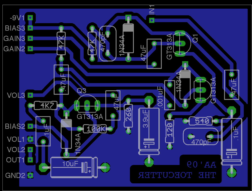
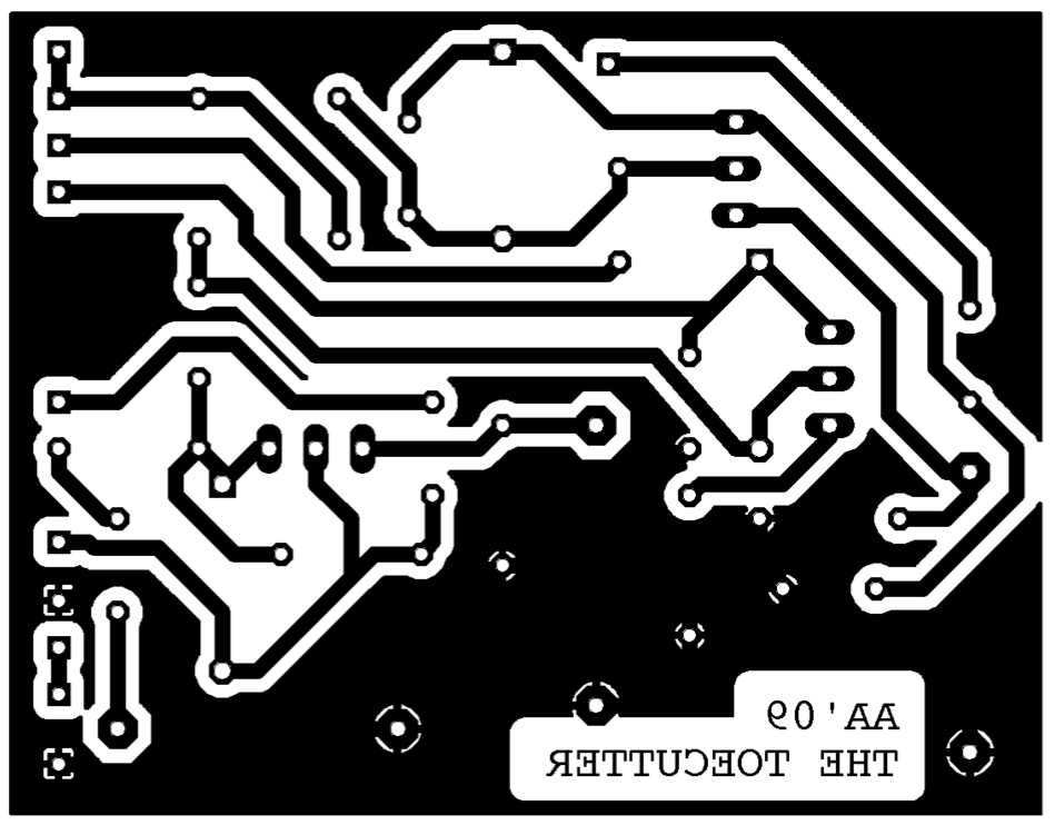
HERE is a link to the Toecutter thread at FSB.org.
XXXXXXXUPDATEXXXXXX
LAYOUT IS VERIFIED.


HERE is a link to the Toecutter thread at FSB.org.
30.1.09
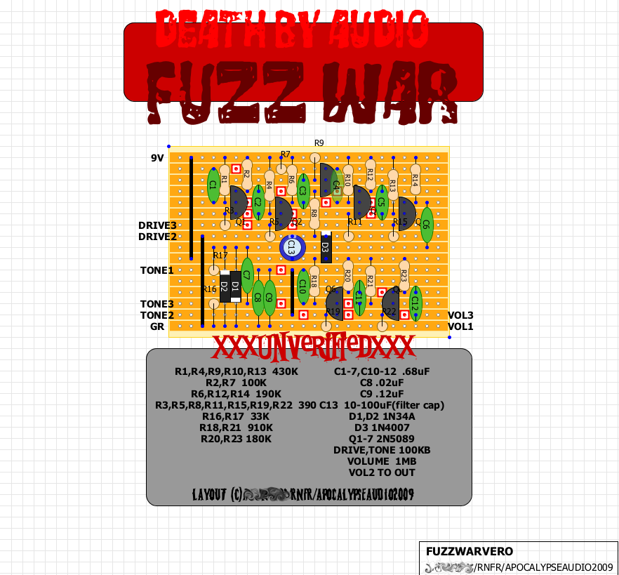
DEATH BY AUDIO- FUZZ WAR
the dba fuzz war got re'd a ways back on freestomp, and some requested a vero layout for it. since i've been trying my hand at the strip layouts lately i thought i'd give it a shot. it's a pretty cool sounding fuzz from the clips that i've heard, extremely thick and nasty. the internal drive control was brought outboard for an extra control, and i added some power filtering as well as deleting some components that weren't being used. you can check out the thread on this unorthodox fuzz design HERE.
the main gain stages in the fuzz war use transistors that are reversed in orientation from the way they would normally be. by placing them backwards, you can take advantage of what is called the reverse beta of the transistor. this is basically how much gain a particular tranny has when it is reversed. check out more in jack orman's article HERE.
the main gain stages in the fuzz war use transistors that are reversed in orientation from the way they would normally be. by placing them backwards, you can take advantage of what is called the reverse beta of the transistor. this is basically how much gain a particular tranny has when it is reversed. check out more in jack orman's article HERE.

28.1.09
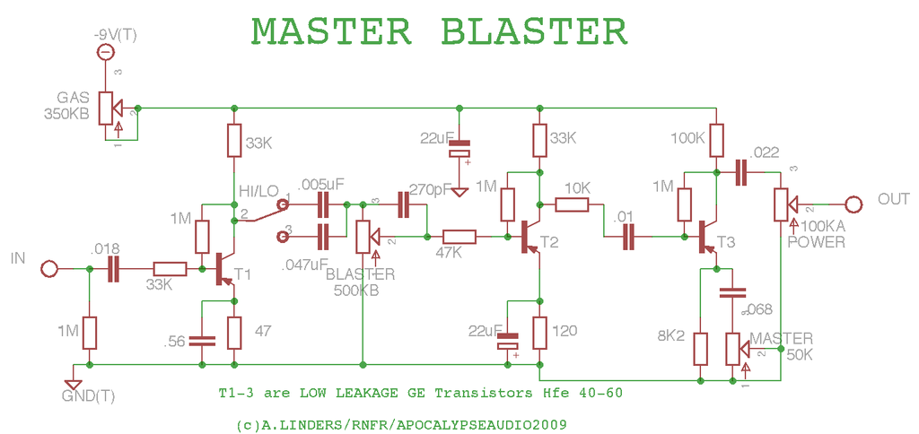
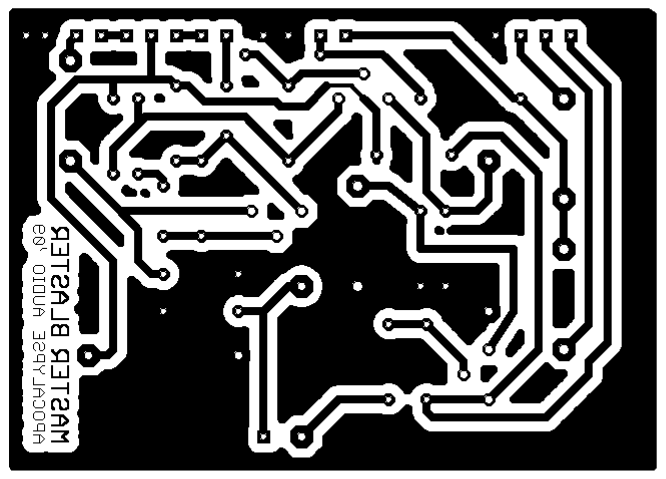
MASTERBLASTER
WHO RUNS BARTER TOWN????
well here's my latest design. this one started out as my attempt at getting an AC30 type tone, but turned into much more. with it you are able to go from a cleanish boost to a light OD, to a fuzz, depending on how you set the controls and how hot your pickups are.
there are 2 gain controls built around a 3 tranny germanium platform using some low leakage soviet ge's with a gain range of around 40-60. the Blaster pot is the main Gain control and the Master control does more of a mid/hi boost in gain. the Blaster pot is set up a bit like the AC30, but there is also the HI/LO switch which basically allows you to go from something like the AC's Top Boost channel to the AC's Normal channel. in the HI position this thing does a great treble booster impersonation with a real glassy, sparkling, top end and can get up to a very tight focused fuzz sound. in the LO position the tone gets filled out a bit and you have another octave on the low end. turn up the Master and Blaster controls and you end up with something like an AC30 crossed with a germanium fuzz. finally there is the Gas control which is your basic voltage starve pot. i found that this thing can survive on extremely low voltage(i ended up using a 350K pot) as there is still plenty of boost to bring the volume up. with the Gas down, the tone gets thicker and crunchier. very cool with your tone rolled off on the guitar as well for a super nasty thick fingerpicking or slide blues fuzz. very lofi! there really are a lot of options with this thing- boost, OD, or fuzz, and it's got tons of hi-mids. it'll cut through a mix for damn sure. i might end up doing a high end roll off pot or switch at the end of the circuit as well, but that's kind of an afterthought.
i have a feeling that this is going to be my go to box for any type of garage/punk/blues kinda stuff. i haven't tried it out with my big amps yet, hopefully soon.
attached is the schematic and PCB layout(unverified- all my shit is packed for the move this weekend). also just so there is no confusion- the layout is made for some larger size components that i wanted to use. hopefully i'll get some sound samples done soon and post em up. thanks to SoulSonic for the help with the extra gain control, Bjorn Juhl, and the Vox AC30 for inspiration. cheers.
jXXXXXUPDATEXXXXXX
just a little heads up. when i intially tested this circuit, i did so with my Airline T&C which has very low output pickups. with mid to high output pickups, it gets into a pretty blazing fuzz with the gain up. this could be tamed by simply putting some resistance in the circuit at the input with a pot. of course you would then be up to 3 gain controls, but hey, that's what this shit is all about right? but seriously, you could replace the Blaster pot with a fixed resistor and all would be well. another option would be to ditch the gas control, and add the pregain. this could be done by those more interested in traditional,"nice" tones.
XXXXXXXXUPDATE- THE PCB LAYOUT IS VERIFIED!!XXXXXXXXXX
XXXXXXXXXXXXXXXUPDATEXXXXXXXXXXXX
- THERE ARE A COUPLE OF ERRORS WITH THE LABELING OF THE POTS AND SWITCHES ON THE LAYOUT, THE GAS AND MASTER POTS SHOULD BE 3 AND 2 INSTEAD OF 1 AND 2. THE SWITCH SHOULD BE 1,3,2 INSTEAD OF 2,3,1 FROM LEFT TO RIGHT. I HAVE A BETTER LAYOUT THAT I WILL POST SOON AS WELL.
ONE MORE THING-
THE MASTER POT IS BETTER AT 25K RATHER THAN 50K.
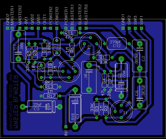
XXXXXXXXXXXXXXXXXUPDATEXXXXXXXXXXXXXXXX
here is a smaller, tighter, layout, for use with normal sized components. unverified as of now, but eagle says it's good.


well here's my latest design. this one started out as my attempt at getting an AC30 type tone, but turned into much more. with it you are able to go from a cleanish boost to a light OD, to a fuzz, depending on how you set the controls and how hot your pickups are.
there are 2 gain controls built around a 3 tranny germanium platform using some low leakage soviet ge's with a gain range of around 40-60. the Blaster pot is the main Gain control and the Master control does more of a mid/hi boost in gain. the Blaster pot is set up a bit like the AC30, but there is also the HI/LO switch which basically allows you to go from something like the AC's Top Boost channel to the AC's Normal channel. in the HI position this thing does a great treble booster impersonation with a real glassy, sparkling, top end and can get up to a very tight focused fuzz sound. in the LO position the tone gets filled out a bit and you have another octave on the low end. turn up the Master and Blaster controls and you end up with something like an AC30 crossed with a germanium fuzz. finally there is the Gas control which is your basic voltage starve pot. i found that this thing can survive on extremely low voltage(i ended up using a 350K pot) as there is still plenty of boost to bring the volume up. with the Gas down, the tone gets thicker and crunchier. very cool with your tone rolled off on the guitar as well for a super nasty thick fingerpicking or slide blues fuzz. very lofi! there really are a lot of options with this thing- boost, OD, or fuzz, and it's got tons of hi-mids. it'll cut through a mix for damn sure. i might end up doing a high end roll off pot or switch at the end of the circuit as well, but that's kind of an afterthought.
i have a feeling that this is going to be my go to box for any type of garage/punk/blues kinda stuff. i haven't tried it out with my big amps yet, hopefully soon.
attached is the schematic and PCB layout(unverified- all my shit is packed for the move this weekend). also just so there is no confusion- the layout is made for some larger size components that i wanted to use. hopefully i'll get some sound samples done soon and post em up. thanks to SoulSonic for the help with the extra gain control, Bjorn Juhl, and the Vox AC30 for inspiration. cheers.
jXXXXXUPDATEXXXXXX
just a little heads up. when i intially tested this circuit, i did so with my Airline T&C which has very low output pickups. with mid to high output pickups, it gets into a pretty blazing fuzz with the gain up. this could be tamed by simply putting some resistance in the circuit at the input with a pot. of course you would then be up to 3 gain controls, but hey, that's what this shit is all about right? but seriously, you could replace the Blaster pot with a fixed resistor and all would be well. another option would be to ditch the gas control, and add the pregain. this could be done by those more interested in traditional,"nice" tones.
XXXXXXXXUPDATE- THE PCB LAYOUT IS VERIFIED!!XXXXXXXXXX
XXXXXXXXXXXXXXXUPDATEXXXXXXXXXXXX
- THERE ARE A COUPLE OF ERRORS WITH THE LABELING OF THE POTS AND SWITCHES ON THE LAYOUT, THE GAS AND MASTER POTS SHOULD BE 3 AND 2 INSTEAD OF 1 AND 2. THE SWITCH SHOULD BE 1,3,2 INSTEAD OF 2,3,1 FROM LEFT TO RIGHT. I HAVE A BETTER LAYOUT THAT I WILL POST SOON AS WELL.
ONE MORE THING-
THE MASTER POT IS BETTER AT 25K RATHER THAN 50K.


XXXXXXXXXXXXXXXXXUPDATEXXXXXXXXXXXXXXXX
here is a smaller, tighter, layout, for use with normal sized components. unverified as of now, but eagle says it's good.


another cool mod is to replace the .0047 cap after the switch with a 470K/470pF combo in parallel. replace the .047uF cap with a .47. this makes the 2 channels very different- one lighter and a bit brighter, and the other thicker and heavier.
15.1.09
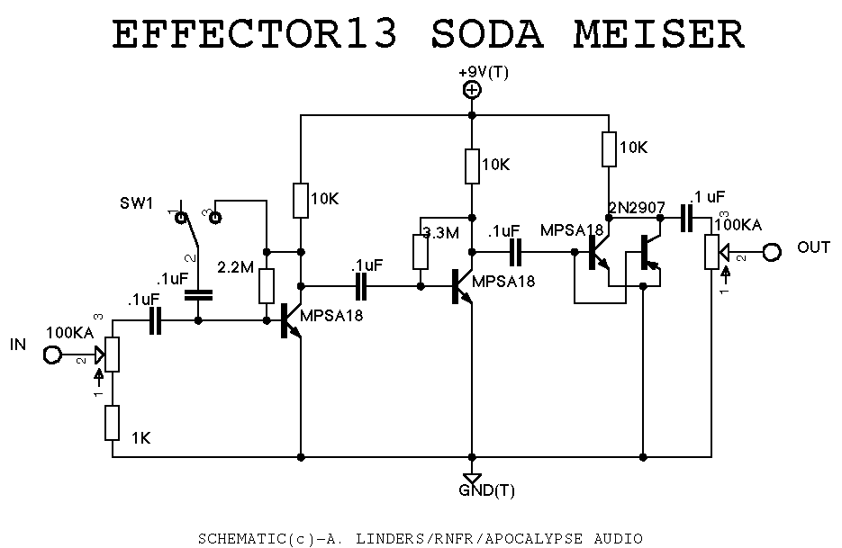
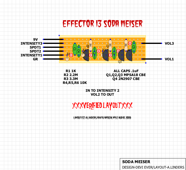
EFFECTOR13- SODA MEISER
dammit- i had a whole article written and it accidentally got erased. fuck it. here's the SM schem and vero- verified. enjoy the squarewaves. click title for the full story. out.


14.1.09
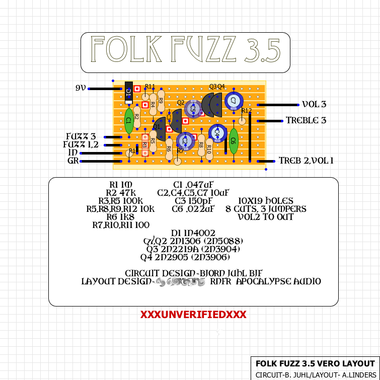
folk fuzz vero
i did up this vero layout today. Torchy had made one already which was just fine, but there were a few things i wanted to change, so i just made my own. mines a bit smaller, and the LED and other wiring is offboard- less connections, less wiring, less breaks AFAIC. this is supposed to be a great sounding design by Bjorn Juhl of BJF ELECTRONICS, AND MAD PROFESSOR. Bjorn's stuff is highly admired in the pedal industry, and he's a cool guy that contributes over at FREESTOMPBOX.ORG now and again. i'll probably breadboard this up soon, and then try out this vero layout. if anyone decides to tackle this thing themselves, let me know!

12.1.09
the od pedal comparinator
this guy set up this pretty cool way to A/B overdrive pedals. he did a bunch of clips of different pedals at different settings and set up this interactive menu for switching between them. it's called the OD COMPARINATOR. one thing that it made me realize is that i think that most overdrive pedals sound like shit. maybe it's just this guy's setup, i don't know. maybe it's the strat. i think he is really into srv so maybe that's the deal. either way, it's a cool idea- but the tones just don't do it for me. i guess i'm just a fuzz guy- what can i say.
amz lab notebook
jack orman's amz webpage has been a staple among diyers for years. in his LAB NOTEBOOK you will find a bunch of great ideas and tips to and tricks to help you along your way. check out his blog, too!
debugging your build
here's a couple invaluable links from geofex dealing with transistors and how they should be biased in your stompbox build. geofex is filled with great information. i've been going there on and off since about 4-5 years ago, and i'm still finding and learning great stuff.
TESTING TRANSISTORS IN THE CIRCUIT
BLATTY OR GATED SOUND
TESTING TRANSISTORS IN THE CIRCUIT
BLATTY OR GATED SOUND
7.1.09
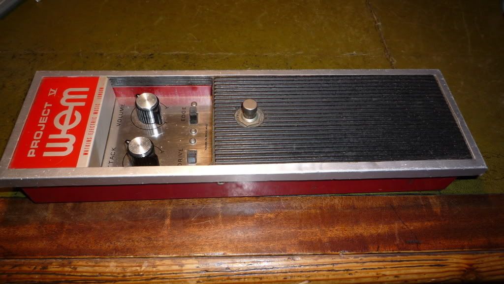
WEM Project V
Graham over at the D*A*M forum showed up recently with picks of this extremely rare 8 transistor fuzz from WEM. truly one of the most unique fuzzes ever made, with next to nothing to find on the net about it, it is a true gift to even get these pics. hopefully sometime in the future we can all get to know what makes her tick a bit better so the love from this apparently amazing sounding fuzz can be spread around for everyone to enjoy. thanks graham!
click on the title above for more pics at the D*A*M forum.
click on the title above for more pics at the D*A*M forum.

Subscribe to:
Posts (Atom)


